How to make a sound amplifier for speakers with your own hands?
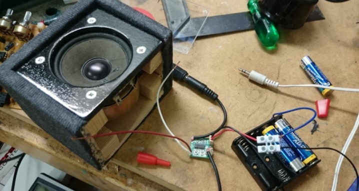
A full-fledged speaker does not work without an amplifier so that music and speech can be heard from it at a decent distance. A low-power preamplifier, which, for example, is equipped with pocket radios and MP3-players, when connected to speakers without a main amplifier, works with overload and may fail. However, craftsmen will be able to make a sound amplifier for speakers with their own hands.
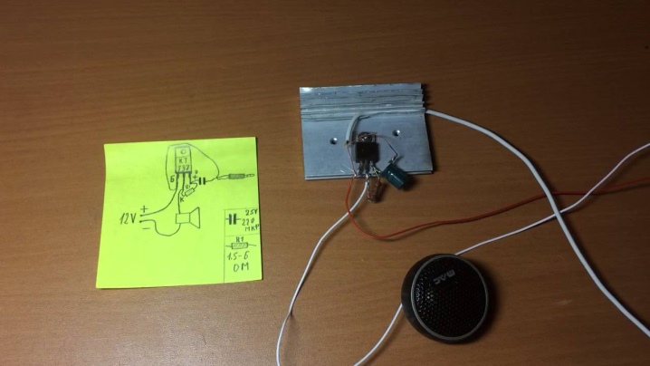
What can be made of?
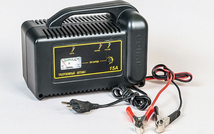
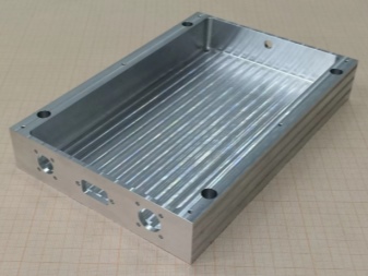
An amplifier for one, two or more speakers at home can be made on the basis of any of the devices, in the case from which its electronic board would fit in length and width. The case can be either the active speaker itself, in which it is installed in a separate, fenced-off space along with the power supply unit, or a powerful charger 0.
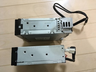
An alternative solution is the housing from the old radio tape recorder, from which the cassette or CD drive, which has expired its service life, has been removed. Often, only a powerful stereo amplifier remains from old car radios - in this case, nothing needs to be altered. If there are no ready-made cases, the case itself is made independently from plywood of small thickness (up to 1 cm), aluminum sheets, double-sided foil fiberglass and other materials.
Manufacturing instruction
A do-it-yourself sound amplifier for speakers will require radio materials and radio components for the manufacture.
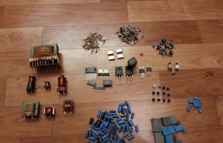
- A set of parts (according to the selected scheme): TDA series microcircuit or similar, resistors, capacitors, test speaker (or already assembled passive speaker), aluminum radiator. When assembling an amplifier on powerful transistors, designed for low frequencies up to 100 kHz, you will need, in addition to the transistors themselves, somewhat less massive radiators.
- Printed circuit board. If the board will not be etched on its own (for example, with ferric chloride), then instead of a simple foil-clad (glass) PCB or getinax, a breadboard with ready-made contact holes is ordered in a Chinese online store, connected using copper wire or pieces of wire with stripped insulation. Fans of etching boards in the classical way will need, in addition to reagents for the preparation of ferric chloride, varnish tightly adhering to metals.
The easiest option is nail polish, but the cost may not be worth it.

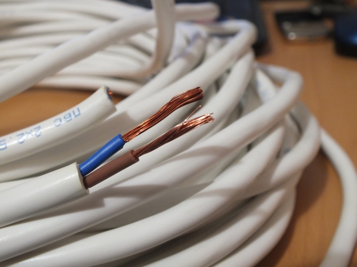
- Electrical wires - any wire with a diameter of 0.5 sq. mm, from which the insulation can be easily removed. It can be a wire of the KSVV (or KSPV) brand. To connect ready-made blocks and nodes, a multi-core ball screw for 0.75 or 1 square meter is most often used. mm.
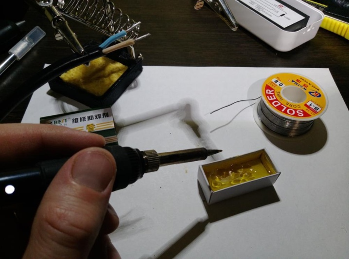
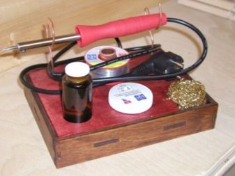
- Solder, rosin and soldering flux for use with a soldering iron. Assembly on roll-ups is unreliable - copper wires, oxidizing, quickly lose contact. Assembly with bolts, nuts and sleeves is too time consuming option.
In addition to materials, some devices and tools are also needed.
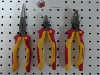
- Pliers, side cutters, screwdriver set... An adjustable wrench and hex wrench set may be required.
- Soldering iron and a stand for him.
- If the board is made "from scratch" - you need a miniature drill and a set of drills. To manufacture a printed circuit board without the use of chemicals, you will need a cutter that traces grooves that separate tracks and other conductive areas.
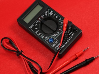
- Multimeter (tester) - almost no electrical work can do without it.
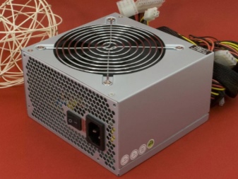
- Test power supply. If there is no such unit, but you know the voltage supplied to the amplifier, start assembling the device from it. It is often much more difficult to get a ready-made 12-volt power supply (all amplifiers with an output power of several watts or more require just such a voltage) than a charger for a smartphone or tablet.
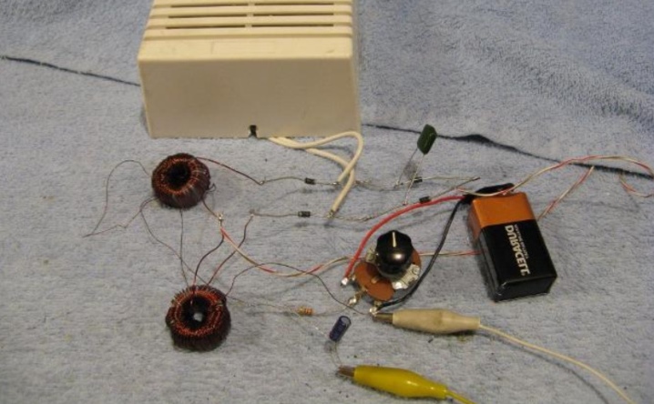
Having prepared all the necessary devices, tools, radio materials and radio components, you can start assembling a homemade device. To manufacture a 10 volt power supply (if the amplifier allows such a voltage drop), connect the leads of the 5 volt chargers in series. A bipolar 10 V power supply is formed with the ability to ground or "zero" the midpoint 0 (where one "minus" and one "plus" are connected in series).
Assembling an amplifier involves a number of steps.
- If the board is not a breadboard, but completely self-assembled - draw with a brush or a tampon the paths with varnish under the microcircuit topology. Hinged elements can be positioned arbitrarily, it is recommended to arrange them more tightly. There should be no intersecting paths.
- Dry the board, prepare a solution of ferric chloride, dip the board into it for several hours or for a day... If the solution is heated, etching will proceed faster, but the likelihood of peeling off the protective layer will significantly increase.
- After etching is complete, remove the varnish from the remaining etch-protected areas. Do not delay the process for several days so that the varnish does not adhere firmly to the board.
- Drill out using a drill or screwdriver, holes for the legs of radio components.
- Cover the resulting tracks with a layer of solder. Insert the radioelements, referring to the assembly drawing, in the required sequence, solder them on the printed circuit board.
- Install the heatsink on the metal base of the microcircuit. If the amplifier circuit is transistorized, use a separate heat sink for each of the output stages. It is allowed to place them on a common radiator.
- Solder the wires to the audio input, power input and sound output, label them.
- Connect speakers to the output of the assembled amplifier.
- Connect an audio source to the input (smartphone, MP3 player or radio) using a 3.5 mm jack.
- Apply power to the appropriate terminals, turn on the sound on the gadget, for example, by choosing any of the available soundtracks (or videos).
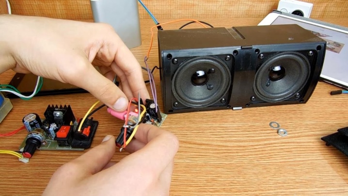
When properly assembled, the amplifier will work immediately. For transistor amplifiers in "stereo" mode, two independent mono amplifiers are used. As a working option - two one-, two-, three- or more cascade devices. The three-stage scheme is the most versatile: the first, low-power stage will "swing" the second (medium power). The second is the third (terminal), which has the maximum power. A radiator is installed on the last stage.
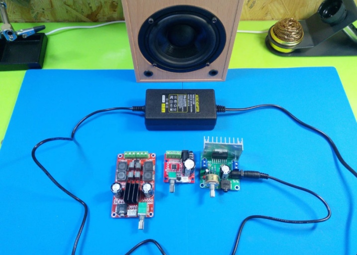
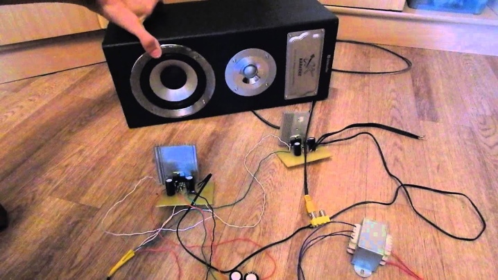
The technology of stereo sound (surround sound) is such that independent amplifiers can be connected separately and have separate speakers. But for stereos in which the subwoofer (subwoofer or speaker) is common, the stereo version of the amplifier is assembled on one microcircuit - both the left and right channels are brought together with the help of additional hinged (passive) parts.
Recommendations
Try not to keep the soldering iron at one point for a long time. - a few seconds of overheating (temperature over 250 degrees) can peel off the copper foil layer, and the track will have to be replaced with copper wire. Due to their greater curvature, wire tracks introduce additional destabilization in the operation of high-frequency electrical circuits and cascades.
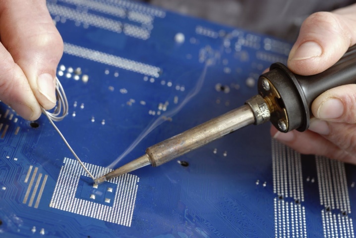
In order not to overheat the microcircuit, transistors and / or diodes (they receive thermal breakdown from overheating), use soldering flux (in the simplest case, this is a zinc chloride solution) or citric acid and some rosin. The evaporating flux partially cools the terminals of the radio components, preventing the latter from overheating. Movements should be clear, but fairly fast.
It is not recommended to use a soldering iron with a power of more than 40 W - a high-power one in a second or more will overheat active radio components.
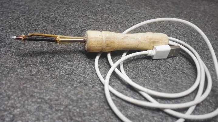
Do not neglect radiators. It is useful to carry out a thermal calculation of the circuit. In this regard, it is easier for graduates of technical universities who have studied at the faculties of radio electronics and equipment design. An amplifier that overheats at a higher volume will sooner or later fail.
Do not overestimate the supply voltage more than the maximum value specified in the circuit instructions. Lack of power will result in the amplifier not working or working at minimum power.
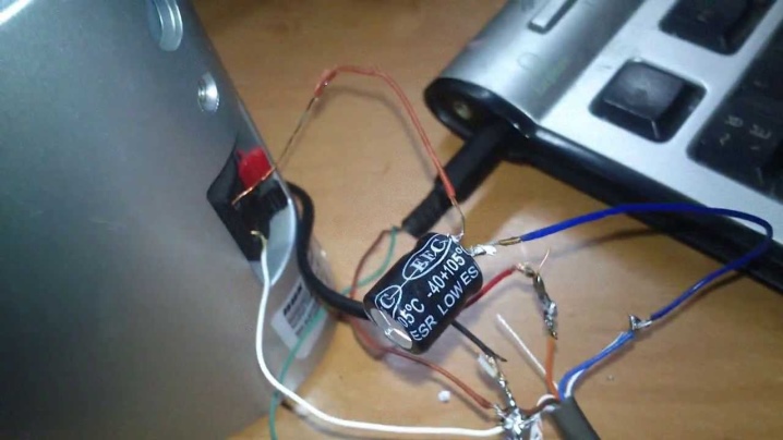
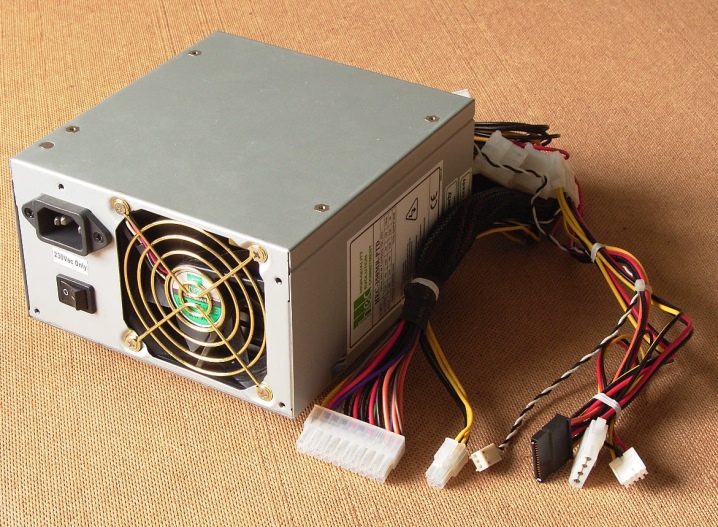
A computer power supply used in a home computer, which has long been outdated in performance, can come in handy - it consumes 250-400 W, but produces at least 70% of this value. Among the output voltages of the computer power supply unit there are 3.3; 5 and 12 V. This is a universal solution for "DIYers" - the power supply from the old PC acts as a laboratory one.
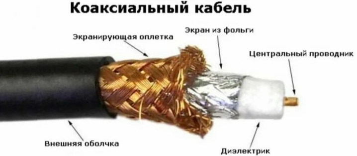
Match (correlate) the power of the speakers and the amplifier. Weak speakers will burn out on a powerful amplifier. The opposite situation is also possible, when the sound in too powerful speakers will "choke". To get rid of interference from the side of the power supply, the input and output of the amplifier are connected by means of a shielded twisted pair - a coaxial cable with two independent central conductors, which plays the role of an acoustic one.
Having decided on the expected parameters, you will assemble a universal amplifier, the power of which (and the speakers for it) is enough to organize listening to music over a large area of several hundred square meters.
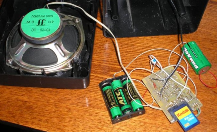
In the next video, you will learn one of the options for creating a do-it-yourself sound amplifier for speakers.


The comment was sent successfully.