Cross planers
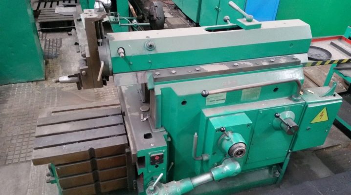
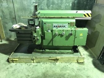
Cross planers are special equipment for cutting small and medium-sized workpieces. The units are distinguished by their compact size and long service life due to their robust design. Manufacturers produce different types of cross planers, it is worth considering the structural features of the equipment in more detail.
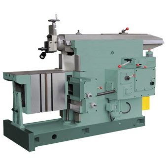
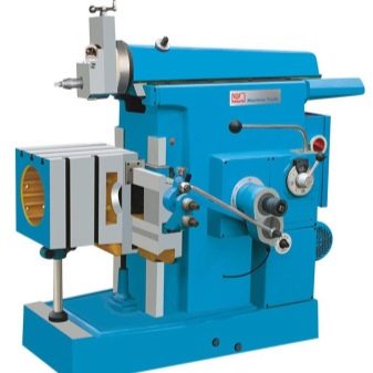
Device and principle of operation
Cross planers are distinguished by their universal purpose, which can be achieved due to a special device. The design is based on the crank-rocker assembly, which is responsible for the position of the slider in the range from 20 to 500 mm. Standard features of any machine.
-
The maximum displacement of the surface on which the part is fixed is from 310 to 500 mm. Interestingly, a lever controlled by the user is responsible for the movement. The average shear rate is 2.23 m / min.
-
The control accuracy of the device is 100 microns.
-
The maximum dimensions of workpieces that the device can process are 380x375 mm on the side surfaces and 500x360 mm on the top.
-
Mounting type - on the legs provided by the design with the help of T-shaped grooves.
-
The maximum vertical displacement of the cutter when the machine is turned on is 170 mm.
-
The maximum angular movement of the head is 60 degrees.
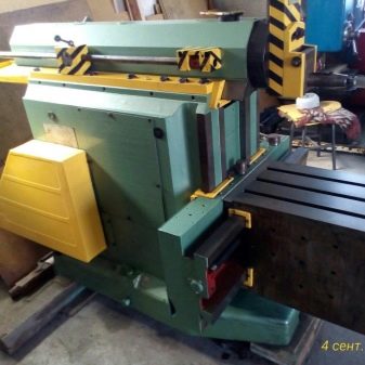
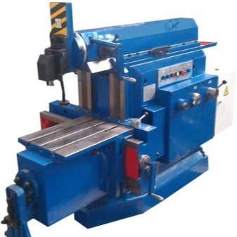
Most models do not have a function that automatically lifts the tool in case of an unexpected stop of the mechanism. However, some modern machines have this option, which makes the equipment more convenient to use. The design of the transverse lathe includes a number of basic components.
-
Emphasis. Additionally, it fixes the table, acting as a fulcrum. Each stop is equipped with a bar that can be manually adjusted.
-
Table. It is necessary for fixing the workpiece with its subsequent transfer to the working area. The surface is capable of moving in both horizontal and vertical planes.
-
Guides. The design includes both horizontal and vertical guides. Responsible for moving the table.
-
Tool holder. Responsible for fixing the cutting element, equipped with a cutter retraction mechanism, which prevents damage to the blade.
-
Caliper. An element used to set the depth of cut and to adjust the reach of the cutter towards the workpiece.
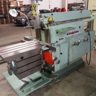
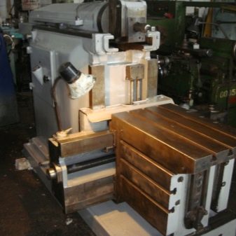
Kinematic machines are equipped with a bed and a crossbeam, which also regulate the movement of the structure. As for the technical parameters, the average machine of this type has the following characteristics:
-
drive type - engine;
-
power - up to 5.5 kW;
-
the maximum number of revolutions per minute - 1400;
-
maximum effort of the slider during operation - 1800 kg;
-
the length of the double table stroke - up to 0.5 m;
-
the maximum permissible cutting speed of the material is 140 m / min.
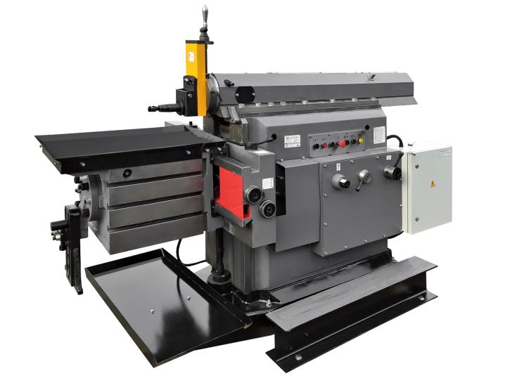
The standard length of the machine is 2335 mm, the height reaches 1540 mm, and the width does not exceed 1355 mm.
Appointment
The main purpose of the equipment is to cut the planes of various workpieces and parts. And also the equipment is used for:
-
the formation of grooves and grooves;
-
milling;
-
grinding.
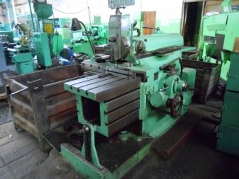
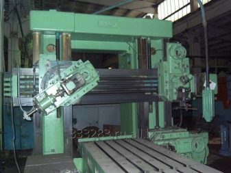
The functionality of the installation for metal cutting is expanded by additional attachments in the form of a milling or grinding head, for example, which is used instead of a support. The heads can be rotated 360 degrees for high quality milling and grinding. In this case, the machine becomes capable of processing elements at different angles.
Another basic purpose of the machine is chip shearing. The scheme of operation of the installation is quite simple: the sliders provided by the design, when moving back, slightly reduce the tractive force compared to the direct working stroke, due to which it is possible to achieve the desired result.
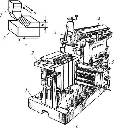
Many craftsmen increase the productivity of the installation by ensuring that the machine is able to cut the chips both during the working stroke and during the return stroke.
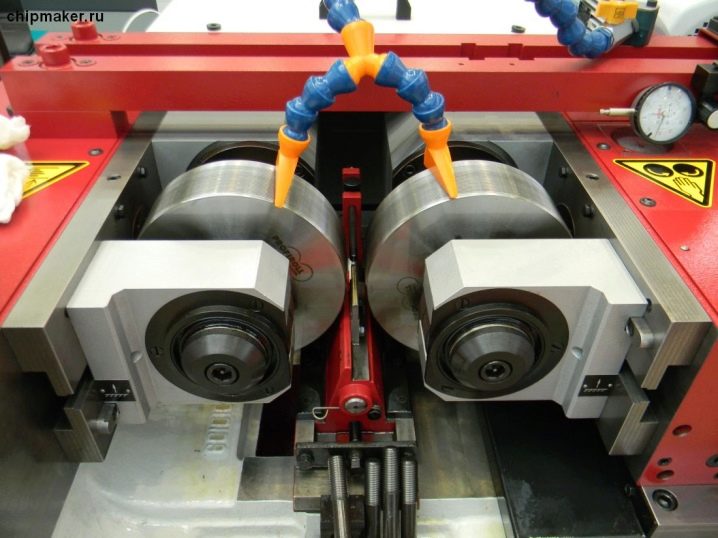
Finally, an additional purpose of the cross planer is thread rolling, carried out using dies and die blocks. The unit is capable of processing fasteners in the form of screws with a diameter of 3 to 6 mm. To form the thread, the machine is equipped with special tools.
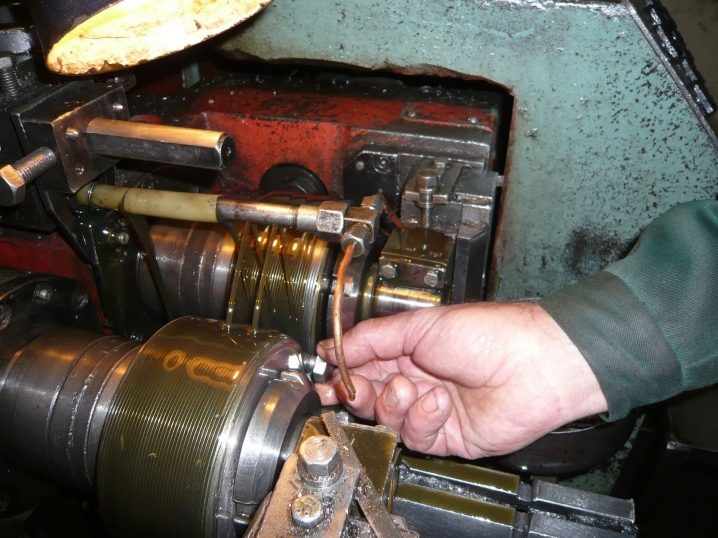
Thread rolling principle.
-
Klupps or dies are placed in the machine. One element is installed on a slider, which is provided in the body and is connected to the tool holder. The second is mounted in a die holder.
-
The slider begins to move, changing the standard position. At this stage, you can adjust the position of the die on the ram holder in the lateral direction.
-
Bolt blanks are placed in the receiver - the magazine of the machine, using manual or mechanical loading.
-
For each double stroke of the slider, the receiver gives out a workpiece, which is taken into operation by a movable die. The element begins to rotate around its axis, rolling onto the fastener and forming a thread.
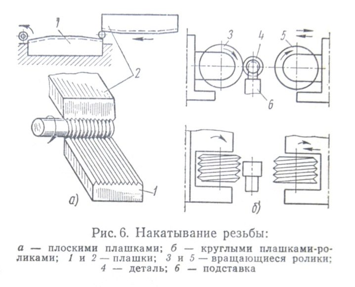
The workpiece is not deformed in the process; on the contrary, the strength characteristics of the part are improved.
Allocate not the direct purpose of the machines.
With the help of the equipment, it is possible to carry out broaching operations. The broach is mounted on a slider or mounted on the installation table.
Manufacturers
The machine tool market is represented by a wide range of cross-planer models from different manufacturers. Among the wide variety, it is worth highlighting a couple of factories that produce reliable equipment.
The main developer of cross-planing equipment is a domestic plant in Orenburg. The models produced by the manufacturer differ:
-
reliable design;
-
excellent performance characteristics;
-
long service life;
-
wide functionality.
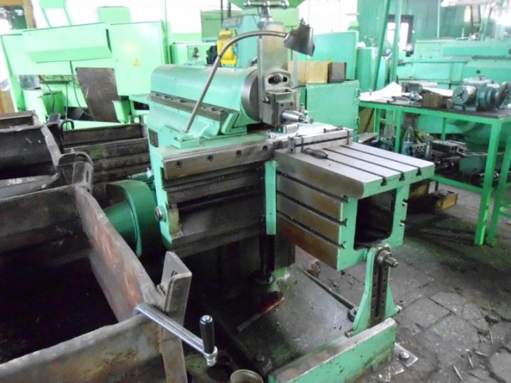
The robust design of the machine ensures efficient operation and quality results. Most of the models are compact, but there are also large installations for processing large workpieces.
The second most popular manufacturer is Gomel SZ. The company produces basic machines equipped with a rotary work surface and copying machines. The equipment is used for processing steel surfaces, the length of the slider does not exceed 700 mm.


The comment was sent successfully.