All about the load on the channel
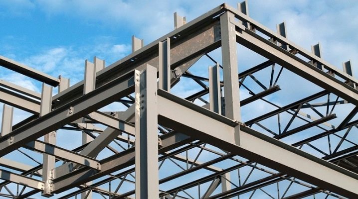
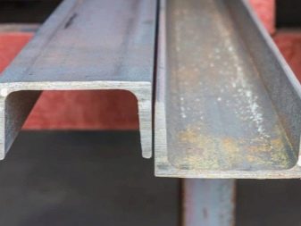
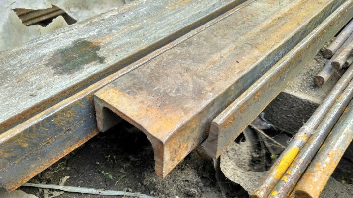
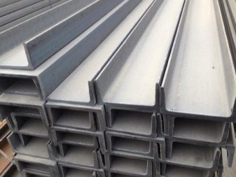
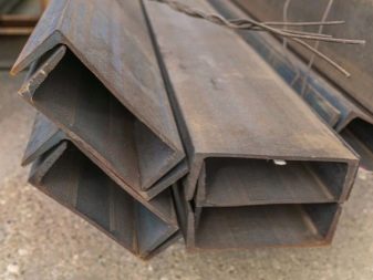
Channel is a popular type of rolled metal, which is actively used in construction. The difference between the profile and other variations of the metal assortment is the special shape of the cross-section in the form of the letter P. The average wall thickness of the finished product ranges from 0.4 to 1.5 cm, and the height can reach 5–40 cm.
Views
The key task of the channel is the perception of loads with their subsequent distribution in order to ensure the stability and durability of the structure in which it is used. During operation, one of the most common types of deformations is deflection, which is what the profile most often experiences. However, this is not the only type of mechanical stress faced by a steel element.
Other loads include allowable and critical bending. At the first, plastic deformation of the product occurs, followed by destruction. When designing metal frames, engineers carry out special calculations in which they determine the bearing capacity of a building, structure and element separately, which allows you to select the optimal cross-section. For successful calculations, designers use the following data:
- normative load that falls on the element;
- type of channel;
- the length of the span covered by the element;
- the number of channels that are laid out next to each other;
- elastic modulus;
- standard sizes.
The calculation of the ultimate load involves standard math. There are several dependencies in the resistance material, thanks to which it is possible to determine the bearing capacity of the element and select its best configuration.
What kind of load can it withstand?
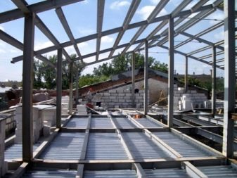
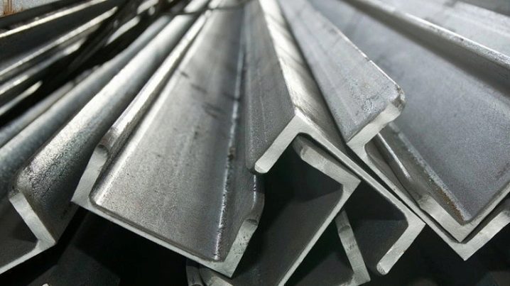
Channel is one of the most popular types of rolled metal, which is used for the construction of steel frames for various buildings and structures. The material mainly works in tension or deflection. Manufacturers produce different profiles with modified cross-sectional dimensions and steel grades, which affects the bearing capacity of the elements. In other words, the type of rolled product determines what kind of load it can withstand, and for channels 10, 12, 20, 14, 16, 18 and other variations, the value of the maximum load will be different.
The most popular are the following brands of channels from 8 to 20, which demonstrate the maximum load-bearing capacity due to the effective configuration of the cross-section. The elements are divided into two groups: P - with parallel edges, Y - with a slope of the shelves. The geometric parameters of the brands, regardless of the group, coincide, the difference lies only in the angle of inclination of the faces and the radius of their rounding.
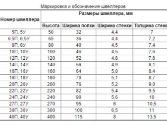
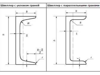
Channel 8
It is mainly used to reinforce steel structures that are inside a building or structure. For the production of such elements, calm or semi-calm carbon steels are used, which ensure high weldability of channels. The product has a small margin of safety, so it holds loads well and does not deform.
Channel 10
It features an increased margin of safety due to its improved cross-section, so designers often choose it. It is in demand both in construction and in the machine-building and machine-tool industries.
Channel 10 is used for bridges, industrial buildings, where the elements are installed as load-bearing supports to form walls.
Payment
The horizontal laying of the channel leads to the need to calculate the loads. First of all, you need to start with a design drawing. In the resistance material, when forming the load diagram, the following types of beams are distinguished.
- Single-span with hinge support. The simplest scheme in which the loads are evenly distributed. As an example, we can single out the profile that is used when constructing interfloor floors.
- Cantilever beam. It differs from the previous one with a rigidly fixed end, the position of which does not change regardless of the types of loading. In this case, the loads are also distributed evenly. Typically, these types of fastening beams are used for the device of the visors.
- Articulated with a console. In this case, the hinges are not under the ends of the beam, but at certain distances, which leads to an uneven distribution of the load.
Beam schemes with the same support options are also considered separately, in which concentrated loads per meter are taken into account. When the scheme is formed, it is necessary to study the assortment, which contains the main parameters of the element.
The third step involves collecting loads. There are two types of loading.
- Temporary. Additionally, they are divided into short-term and long-term. The former include wind and snow loads and the weight of people. The second category involves exposure to temporary baffles or a layer of water.
- Permanent. Here it is necessary to take into account the weight of the element itself and the structures that rest on it in the frame or node.
- Special. Represent the loads that arise in unforeseen situations. This could be the impact of an explosion or seismic activity in the area.
When all the parameters are determined, and the diagram is drawn up, you can proceed to the calculation using mathematical formulas from the joint venture of metal structures. Calculating a channel means checking it for strength, deflection and other conditions. If not, their cross-section of the element is increased if the structure does not pass, or reduced if there is a large margin.

The moment of resistance of the channel in the design of floors
The design of interfloor or roof ceilings, load-bearing metal structures requires, in addition to the basic calculation of the load, additional calculations to determine the rigidity of the product. According to the conditions of the joint venture, the deflection value should not exceed the permissible values specified in the table of the normative document in accordance with the brand of the channel.
Checking the rigidity is a prerequisite for design. List the stages of calculation.
- First, a distributed load is collected, which acts on the channel.
- Further, the moment of inertia of the channel of the selected brand is taken from the assortment.
- The third stage involves determining the value of the relative deflection of the product using the formula: f / L = M ∙ L / (10 ∙ Е ∙ Ix) ≤ [f / L]. It can also be found in the joint venture of metal structures.
- Then the moment of resistance of the channel is calculated. This is a bending moment, which is determined by the formula: M = q ∙ L2 / 8.
- The last point is the definition of the relative deflection by the formula: f / L.
When all the calculations are done, it remains to compare the resulting deflection with the standard value according to the corresponding SP. If the condition is met, the selected channel brand is considered relevant. Otherwise, if the value is much higher, select a larger profile.
If the result is much lower, then a channel with a smaller cross-section is preferred.


The comment was sent successfully.