How to make a radio receiver with your own hands?
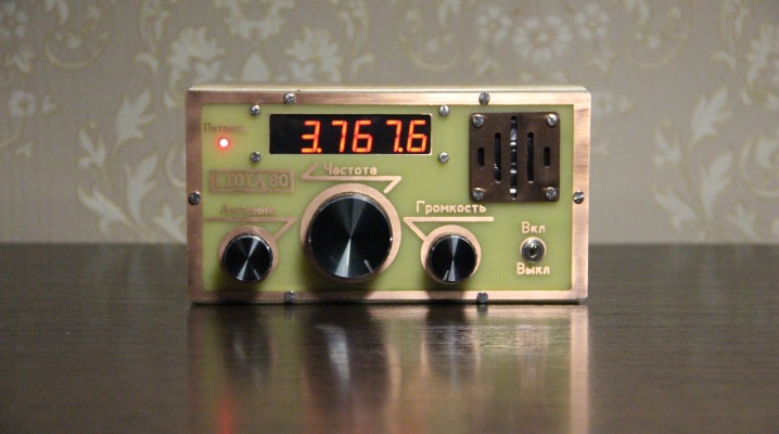
A self-assembled radio receiver includes an antenna, a radio card and a device for playing the received signal - a loudspeaker or headphones. The power supply can be either external or built-in. The accepted range is scaled in kilohertz or megahertz. Radio broadcasting uses only kilo and megahertz frequencies.
Basic manufacturing rules
A home-made receiver must be mobile or transportable. Soviet radio tape recorders VEF Sigma and Ural-Auto, the more modern Manbo S-202 are an example of this.
The receiver contains a minimum of radio elements. These are several transistors or one microcircuit, without taking into account the attached parts in the circuit. They don't have to be expensive. A broadcast receiver costing a million rubles is almost a fantasy: this is not a professional walkie-talkie for the military and special services. The quality of the reception should be acceptable - without unnecessary noise, with the ability to listen to the whole world on the HF band while traveling across countries, and on VHF - to move away from the transmitter for tens of kilometers.
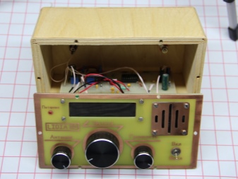
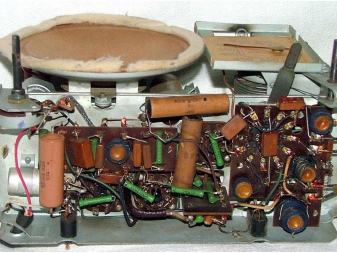
We need a scale (or at least a marking on the tuning knob) that allows you to estimate which range and which frequency is being listened to. Many radio stations remind listeners of what frequency they are broadcasting. But repeating 100 times a day, for example, "Europe Plus", "Moscow 106.2" is no longer in vogue.
The receiver must be dust and moisture resistant. This will provide the body, for example, from a powerful speaker, which has rubber inserts. You can also make such a case yourself, but it is hermetically sealed from almost all sides.
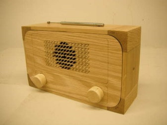
Tools and materials
As consumables will be required.
- A set of radio parts - the list is compiled according to the selected scheme. We need resistors, capacitors, high-frequency diodes, home-made inductors (or chokes instead of them), high-frequency transistors of low and medium power. The assembly on microcircuits will make the device small-sized - smaller than a smartphone, which cannot be said about the transistor model. In the latter case, a 3.5 mm headphone jack is required.
- The dielectric plate for the printed circuit board is made of scrap materials that are not conductive.
- Screws with nuts and lock washers.
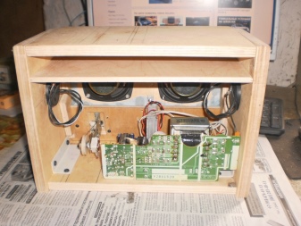
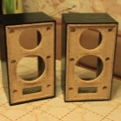
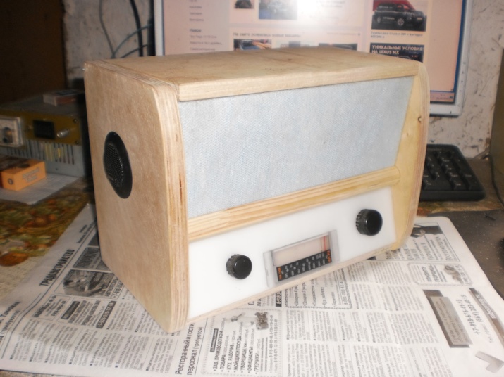
- The case - for example, from an old speaker. The wooden case is made of plywood - you will also need furniture corners for it.
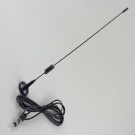
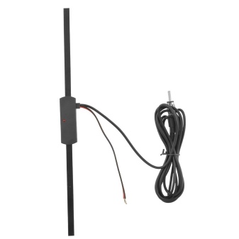
- Antenna. Telescopic (it is better to use a ready-made one), but a piece of insulated wire will do. Magnetic - self-winding on the ferrite core.
- Winding wire of two different cross-sections. A thin wire winds a magnetic antenna, a thick wire winds the coils of oscillatory circuits.
- Power cord.
- Transformer, diode bridge and stabilizer on a microcircuit - when powered from mains voltage. A built-in power adapter is not required for power from rechargeable batteries the size of a regular battery.
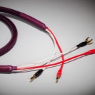
- Indoor wires.

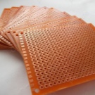
Instruments:
- pliers;
- side cutters;
- a set of screwdrivers for minor repairs;
- hacksaw for wood;
- manual jigsaw.
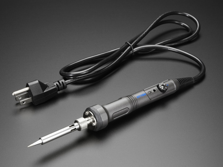
You will also need a soldering iron, as well as a stand for it, solder, rosin and soldering flux.
How to assemble a simple radio receiver?
There are several radio receiver circuits:
- detector;
- direct amplification;
- (super) heterodyne;
- on the frequency synthesizer.
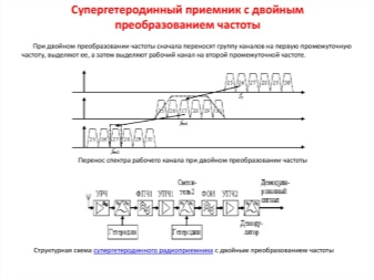
Receivers with double, triple conversion (2 or 3 local oscillators in the circuit) are used for professional work at the maximum permissible, ultra-long distances.
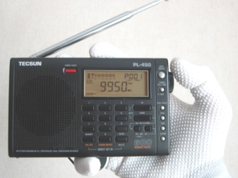
The disadvantage of the detector receiver is low selectivity: the signals of several radio stations are heard simultaneously. The advantage is that there is no separate power supply: the energy of the incoming radio waves is enough to listen to the broadcast without powering the entire circuit. In your area, at least one repeater should broadcast - in the range of long (148-375 kHz) or medium (530-1710 kHz) frequencies. If you are 300 km or more away from it, you are unlikely to hear anything. It should be quiet around - it is better to listen to the transmission in headphones with high (hundreds and thousands of ohms) impedance. The sound will be barely audible, but it will be possible to make out speech and music.
The detector receiver is assembled as follows. The oscillating circuit consists of a variable capacitor and a coil. One end connects to an external antenna. Grounding is supplied through the building circuit, pipes of the heating network - to the other end of the circuit. Any RF diode is connected in series with the circuit - it will separate the audio component from the RF signal. A capacitor is connected to the resulting assembly in parallel - it will smooth out the ripple. To extract sound information, a capsule is used - the resistance of its winding is at least 600 ohms.
If you disconnect the earphone from the DP and send a signal to the simplest sound amplifier, then the detector receiver will become a direct amplification receiver. By connecting to the input - to the loop - a radio frequency amplifier of the MW or LW range, you will increase the sensitivity. You can move away from the AM repeater up to 1000 km. A receiver with the simplest diode detector does not work in the (U) HF range.
To improve adjacent channel selectivity, replace the detector diode with a more efficient circuit.
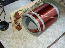
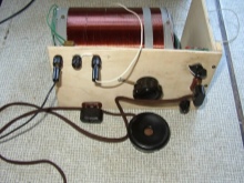
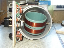
To provide selectivity on the adjacent channel, you need a local oscillator, a mixer and an additional amplifier. The heterodyne is a local oscillator with a variable circuit. The heterodyne receiver circuit works as follows.
- The signal comes from the antenna to a radio frequency amplifier (RF amplifier).
- The amplified RF signal passes through the mixer. The local oscillator signal is superimposed on it. The mixer is a frequency subtractor: the LO value is subtracted from the input signal. For example, to receive a station on 106.2 MHz in the FM band, the LO frequency must be 95.5 MHz (10.7 remains for further processing). The value of 10.7 is constant - the mixer and the local oscillator are tuned synchronously. The mismatch of this functional unit will immediately lead to the inoperability of the entire circuit.
- The resulting intermediate frequency (IF) of 10.7 MHz is fed to the IF amplifier. The amplifier itself performs the function of a selector: its bandpass filter cuts the spectrum of the radio signal to a band of only 50-100 kHz. This ensures selectivity in the adjacent channel: in the densely packed FM range of a large city, radio stations are located every 300-500 kHz.
- Amplified IF - a signal ready to be transferred from the RF to the audio range. An amplitude detector converts the AM signal into an audio signal, extracting the low frequency envelope of the radio signal.
- The resulting audio signal is fed to a low frequency amplifier (ULF) - and then to a speaker (or headphones).
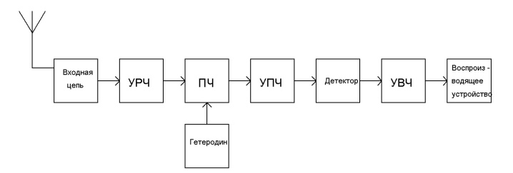
The advantage of the (super) heterodyne receiver circuit is satisfactory sensitivity. You can move away from the FM transmitter for tens of kilometers. Selectivity on the adjacent channel will allow you to listen to the radio station you like, and not a simultaneous cacophony of several radio programs. The disadvantage is that the entire circuit requires power supply - several volts and up to tens of milliamperes of direct current.
There is also selectivity for the mirror channel. For AM receivers (LW, MW, HF bands), the IF is 465 kHz. If in the MW range the receiver is tuned to a frequency of 1551 kHz, then it will "catch" the same frequency at 621 kHz. The mirror frequency is equal to twice the IF value subtracted from the transmitter frequency. For FM (FM) receivers operating with the VHF range (66-108 MHz), the IF is 10.7 MHz.
So, the signal from an aviation radio ("mosquito") operating at 121.5 megahertz will be received when the receiver is tuned to 100.1 MHz (minus 21.4 MHz). To eliminate the reception of interference in the form of a "mirror" frequency, an input circuit is connected between the RF amplifier and the antenna - one or more oscillatory circuits (a coil and a capacitor connected in parallel). The disadvantage of a multi-circuit input circuit is a decrease in sensitivity, and with it the range of reception, which requires connecting an antenna with an additional amplifier.
The FM receiver is equipped with a special cascade that converts FM into AM oscillations.
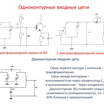
The disadvantage of heterodyne receivers is that the signal from the local oscillator without an input circuit and in the presence of feedback from the RF amplifier enters the antenna and is re-emitted on the air. If you turn on two such receivers, tune them to the same radio station, and place them side by side, close - in the speakers, both will have a slight whistling of a changing tone. In a circuit based on a frequency synthesizer, the local oscillator is not used.
In FM stereo receivers, a stereo decoder is located after the IF amplifier and the detector. Stereo coding at the transmitter and decoding at the receiver are carried out using pilot tone technology. After the stereo decoder, a stereo amplifier and two speakers (one for each channel) are installed.
Receivers that do not have a stereo decoding function receive stereo broadcast in monaural mode.
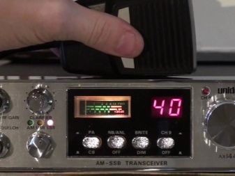
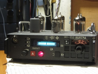
To assemble the receiver electronics, do the following.
- Drill holes in the workpiece for the radio board, referring to the drawings (topology, arrangement of elements).
- Place radioelements.
- Wind up the loop coils and magnetic antenna. Place them according to the diagram.
- Make the paths on the board, referring to the layout in the drawing. The tracks are performed by both teething and etching.
- Solder the parts on the board. Check the correctness of the installation.
- Solder wires to the antenna input, power supply and speaker output.
- Install controls and switches. The multi-range model will require a multi-position switch.
- Connect speaker and antenna. Turn on the power supply.
- The speaker will show the noise of an un-tuned receiver. Turn the tuning knob. Tune in one of the available stations. The sound of the radio signal should be free of wheezing and noise. Connect an external antenna. Need tuning coils, range shift. Choke coils are tuned by rotating the core, frameless ones by stretching and compressing the turns. They need a dielectric screwdriver.
- Select the extreme frequency on the FM-modulator (for example, 108 MHz) and move the turns of the heterodyne coil (it is located next to the variable capacitor) so that the upper end of the receiver's range will steadily receive the modulator signal.
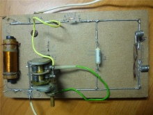
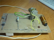
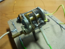
Assemble the case:
- Mark and cut plywood or plastic into 6 edges of the future body.
- Mark and drill the corner holes.
- Saw out a round large speaker gap.
- Cut out the slots from the top and / or the side for the volume control, power switch, band switch, antenna and frequency control knob, guided by the assembly drawing.
- Install the radio board on one of the walls using pile-type screw posts. Align the controls with the access holes on the adjacent body edges.
- Mount the power supply - or USB board with lithium-ion battery (for mini radios) - away from the main board.
- Connect the radio board to the power supply board (or to the USB controller and battery).
- Connect and secure the magnetic antenna for AM and the telescopic antenna for FM. Insulate all wire connections.
- If a loudspeaker model is made, install the speaker on the front edge of the cabinet.
- Using corners, connect all the edges of the body to each other.
For the scale, graduate the adjustment knob, put a mark in the form of an arrow next to it on the body. Install LED for backlight.
Recommendations for beginners
- In order not to overheat diodes, transistors and microcircuits, do not work with a soldering iron with a power of more than 30 watts without flux.
- Do not expose the receiver to rainfall, fog and frost, acid fumes.
- Do not touch the terminals of the high-voltage part of the power supply when the device under test is energized.
How to assemble a radio with your own hands, see below.


The comment was sent successfully.