Tube radios: device, operation and assembly
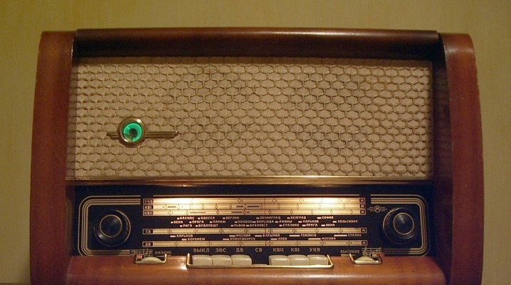
Tube radios have been the only signal reception option for decades. Their device was known to everyone who knew a little about technology. But even today, the skills of assembling and operating receivers can be useful.
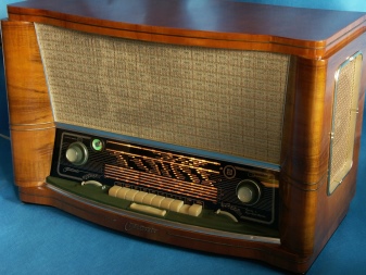
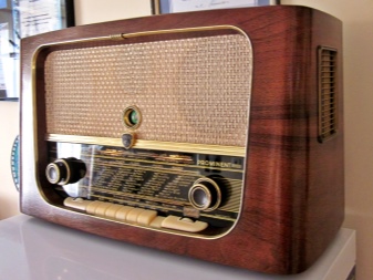
Device and principle of operation
A complete description of the tube radio will, of course, require extensive material and will be designed for an audience with engineering knowledge. For novice experimenters, it will be much more useful to disassemble the circuit of the simplest receiver of the amateur band. The antenna receiving the signal is structured in approximately the same way as in a transistor device. The differences relate to the further link of signal processing. And the most important of them is such radio components as electronic tubes (which gave the name to the device).
The weak signal is used to control the more powerful current flowing through the lamp. An external battery provides increased current through the receiver.
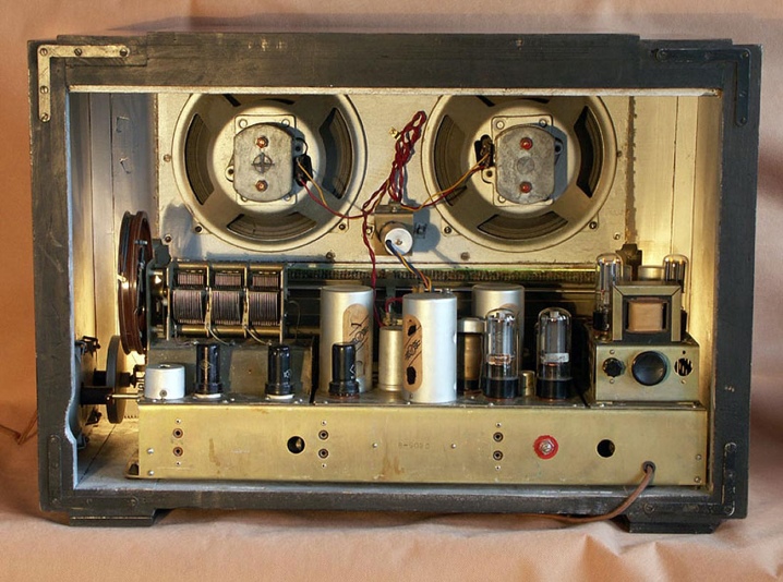
Contrary to popular belief, such receivers can be made not only on glass lamps, but also on the basis of metal or metal-ceramic cylinders. Since there are almost no free electrons in a vacuum environment, a cathode is introduced into the lamp.
The escape of free electrons outside the cathode is achieved by strong heating. Then the anode comes into play, that is, a special metal plate. It ensures the orderly movement of electrons. An electric battery is placed between the anode and cathode. The anode current is controlled by a metal mesh, positioning it as close as possible to the cathode and allowing it to be "locked" electrically. The combination of these three elements ensures the normal operation of the device.
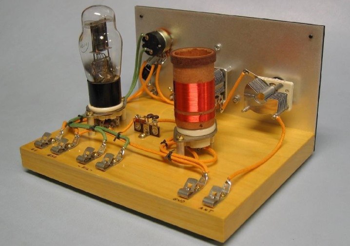
Of course, this is only a basic schematic diagram. And the real wiring diagrams in radio factories were more complicated. This was especially true of the late models of the upper class, assembled on improved types of lamps, which were impossible to make in artisanal conditions. But with a set of components that are sold today, it is possible to create both shortwave and longwave (even 160 meters) receivers.
The so-called regenerative devices deserve special attention. The bottom line is that one of the stages of the frequency amplifier has positive feedback. The sensitivity and selectivity is higher than in the traditional version. However, overall job stability is less. In addition, unpleasant spurious radiation appears.
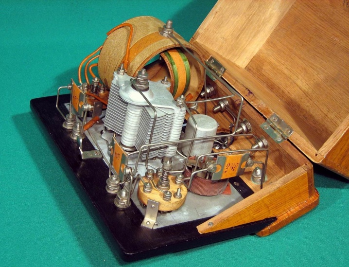
Chokes in receiving devices are used so that the output voltage rises smoothly, without surges. The ripple voltage is determined by the characteristics of the connected capacitor. But already with a capacitor capacitance of 2.2 μF, better results are achieved than when using capacitive power supply filters of 440 μF. A special converter is needed to convert the device from VHF to A | FM. And some of the models are even equipped with transmitters, which greatly expands the capabilities of users.
Production history
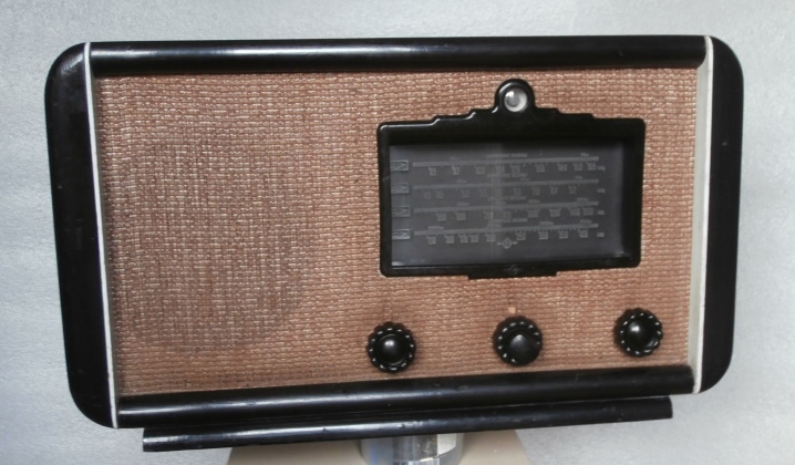
The oldest ones with good reason can be called not tube radios, but detector radios. It was the transition to tube technology that turned radio engineering upside down. The works carried out in our country at the turn of the 1910s - 1920s were of great importance in its history.At that moment, receiving and amplifying radio tubes were created and the first steps were taken to create a full-fledged broadcasting network. In the 1920s, along with the rise of the radio industry, the variety of lamps increased rapidly.
Literally every year, one or more new designs appeared. But those old radios that are attracting the attention of amateurs today appeared much later.
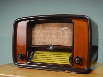
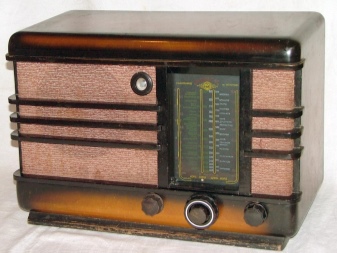
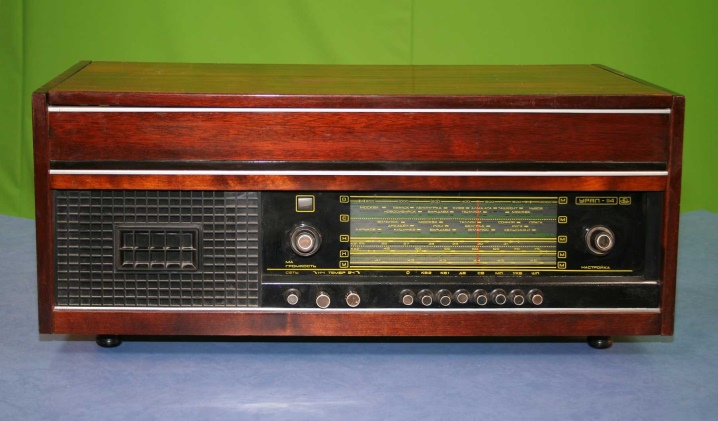
The oldest of them used tweeters. But it is much more important, of course, to characterize the best designs. The Ural-114 model has been produced since 1978 in Sarapul.
The network radio is the latest tube model of the Sarapul plant. It differs from previous models of the same enterprise by a push-pull amplifier stage. A pair of loudspeakers is placed on the front panel. There is also a variation of this 3-speaker radio. One of them was responsible for the high frequencies, and the other two for the low frequencies.
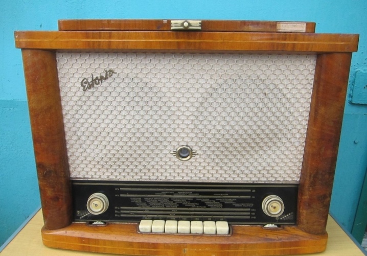
Another high-end tube radio - "Estonia-Stereo"... Its production began in 1970 at a Tallinn enterprise. The package included a 4-speed EPU and a pair of speakers (3 speakers inside each speaker). The reception range covered a wide variety of waves - from long to VHF. The output power of all ULF channels is 4 W, the current consumption reaches 0.16 kW.
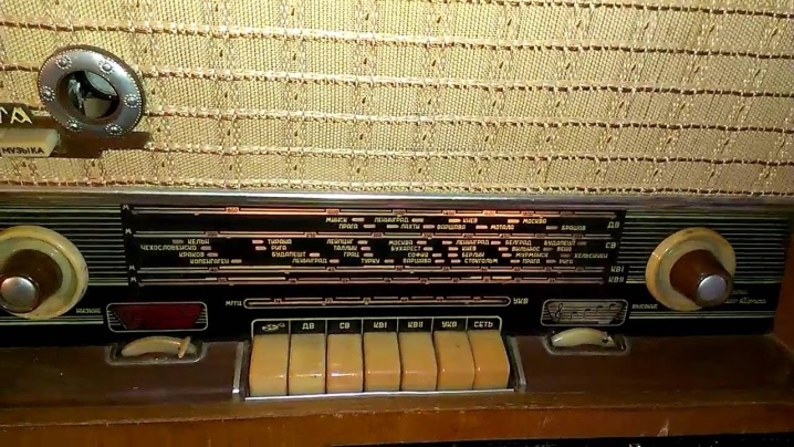
Regarding the model "Rigonda-104", then it was not produced (and was not even designed). But the attention of users has invariably attracted "Rigonda-102"... This model was produced approximately from 1971 to 1977. It was a 5-band monophonic radio. 9 electronic tubes were used to receive the signal.
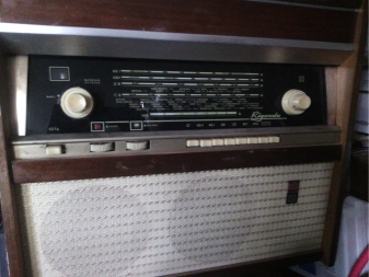
Another legendary modification - "Record". More precisely, "Record-52", "Record-53" and "Record-53M"... The digital index of all these models shows the year of manufacture. In 1953, the loudspeaker was replaced and the device was redesigned. Technical specifications:
- sound from 0.15 to 3 kHz;
- current consumption 0.04 kW;
- weight 5.8 kg;
- linear dimensions 0.44x0.272x0.2 m.
Maintenance and repair
Many tube radios are now in an unsightly condition. Their restoration implies:
- general disassembly;
- removal of dirt and dust;
- gluing the seams of the wooden case;
- quartzization of the internal volume;
- cleaning the fabric;
- flushing the scale, control knobs and other working elements;
- cleaning of tuning blocks;
- blowing out dense components with compressed air;
- testing of low frequency amplifiers;
- check of reception loops;
- diagnostics of radio tubes and lighting devices.
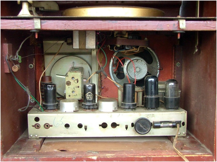
Setting up and adjusting tube radios differs little from the same procedure for their transistor counterparts. Sequentially adjust:
- detector stage;
- IF amplifier;
- heterodyne;
- input circuits.
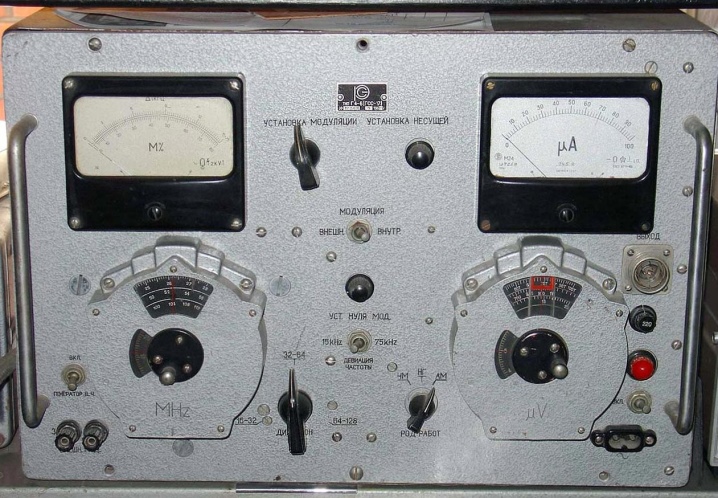
In the absence of it, they use tuning by ear for the perception of radio stations. For this, however, an avometer is needed. Do not connect tube voltmeters to grids.
In receivers with multiple bands, set HF, LW and MW in sequence.
How to assemble with your own hands?
Old designs are attractive. But you can always assemble homemade tube receivers. The shortwave device contains a 6AN8 lamp. It simultaneously functions as a regenerative receiver and an RF amplifier. The receiver outputs sound to the headphones (which is quite acceptable in road conditions), and in normal mode it is a tuner with the subsequent amplification of low frequencies.
Recommendations:
- make a case from thick aluminum;
- observe the winding data of the coils and the diameter of the body according to the diagram;
- supply the power supply with a transformer from any old radio;
- a bridge rectifier is not worse than a device with a midpoint;
- use assembly kits based on the 6Zh5P finger pentode;
- take ceramic capacitors;
- supply lamps from a separate rectifier.
See below for an overview of the RIGA 10 tube radio receiver.


The comment was sent successfully.