FM antennas for music centers: types and methods of creating with your own hands
The quality of modern, especially Chinese inexpensive radios is such that an external antenna and amplifier are indispensable. This problem arises in villages and villages very remote from cities, as well as with frequent travels around the region.
What it is?
An FM radio antenna is a device that improves the reception of radio broadcasts... It is used when the signal from the desired station is insufficient for high-quality radio reception.
It is often used at the highest height above the listener that can be achieved.
Views
Depending on the specific type, the antenna can be active or passive. Antenna type is determined based on its radiation pattern. This is an area of space in which the maximum (antinode) of the main radiation of the transmitted (or received) radio signal is concentrated. Sharp directional antennas are needed so that the signal does not propagate in those directions where it is not needed. Birds and astronauts do not need terrestrial FM broadcasting, and omnidirectional radiation would lead to an overconsumption of electricity when operating a broadcasting transmitter. Instead of 15-kilowatt radiation in the FM-range (66 ... 108 megahertz), one kilowatt would be enough for a population with the same coverage area (within a radius of up to 100 km).
Active and passive
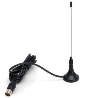
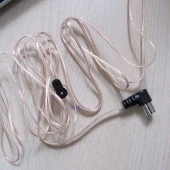
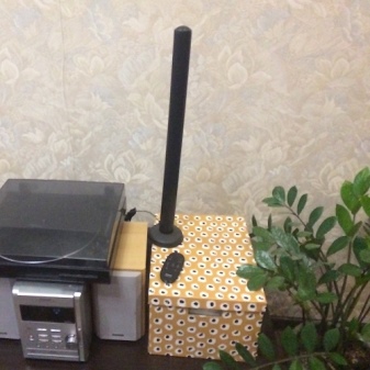
An active antenna helps to strengthen the signal. Sometimes it is equipped with a radio amplifier (along the radius of the radio station's coverage, it is also called a radio extension). The active antenna specifications indicate the decibel value added to the gain of the FM receiver itself. Aggregates are passive (0 dB) and active (1… 6 dB).
The passive ones include pin-type ones, the active ones - improved designs with a reinforcing counterweight.
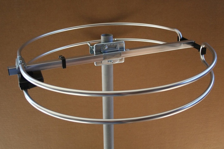
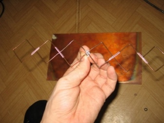
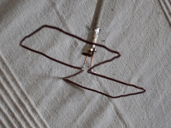
- Loopback. They consist of a single part - a loop vibrator, to one end of which the braid of the cable is connected, to the other - its central conductor.
- "Eight" ("butterflies"). To improve reception, two "eights" are soldered, located at right angles to each other.
- Symmetrical vibrator - two multidirectional pins. A variety is a turnstile antenna: two vibrators, mutually located at right angles.
- "Director" - are the best option. Signal pins guiding in one direction (“directors”) - from 6 to 10 pieces. This is followed by a loop vibrator. Next comes the reflector (reflector) - the mesh or the largest pin. The directors and reflector are isolated from each other and from the vibrator. All parts are located parallel but perpendicular to the direction of the signal.
- Log-periodic - remind the director. The “directors” are shortened by half and are oppositely directed, they stand in a “checkerboard” pattern.
- "Plate" or disc - a ruler of dipoles or a loop ("butterfly") vibrator next to the disc, which reflects the signal on it.
In practice, an extremely effective and cheap option is chosen.
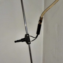
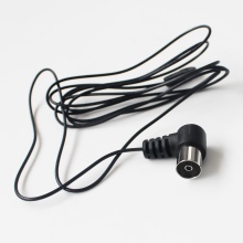
Disk
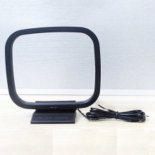
Disc antenna - satellite dish option... Instead of a receiving head with an amplifier - "butterfly" or telescopic pins (symmetrical vibrator). Disc reflector - an old compact disc (contains an aluminum substrate), any metal mesh with cells, the size of which is ten times smaller than the wavelength at the desired frequency.
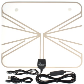
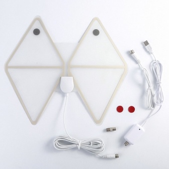
Rod
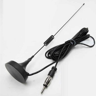
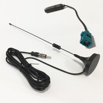
Rod antenna - Any rod at 25% of the wavelength.For the FM band, this is about 3 m (frequencies 87.5 ... 108 MHz), the length of the pin is about 75 cm.
Equipped with right angle counterweights.
Frame
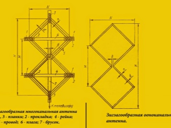
"Eight", if it is one, is located on a reinforcing base, for example, a plate made of plastic or impregnated and painted pieces of wood. The conductor can be a thin profile, cut plates, "etched" foil (glass) textolite or getinax. This design is often used in highly directional automotive antennas.
Wire
This is almost any construction where copper or aluminum wire serves as the main conductor.... Phased antenna arrays that are not made from microstrip or slot lines and pieces of waveguide, but from pieces of wire or wire soldered into a lattice structure, can be considered wire. But this design is also much more expensive.
They are no longer used in radio broadcasting, but in digital and analog radio amateur, for military needs and civil mobile communications.
How to choose?
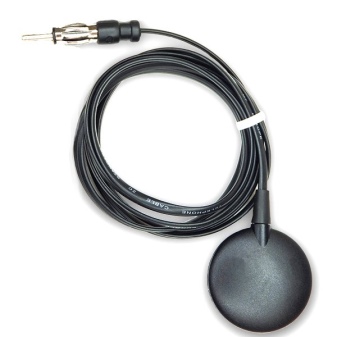
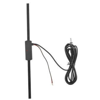
The finished antenna is selected from the assortment provided by Russian and Chinese online stores. This is the only option for those who do not have a radio market or radio store in the regional center or the nearest city. It is easier for people who know something else about radio communications to choose an inexpensive antenna, which will even provide reception of FM radio stations from nearby regional centers and villages from a distance of even 100-150 km. To overcome the noise (when the FM tuner does not have noise suppression in the music center), an additional antenna amplifier is required.
How to do it yourself?
You will need.
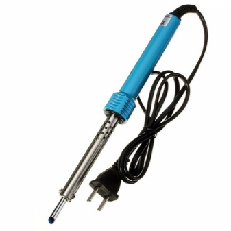
- Soldering iron, solder and rosin, soldering flux. Instead of the latter, zinc chloride was previously used - it is prepared from tablets containing hydrochloric acid. Such tablets are used by stomach patients. As a source of zinc - any alkaline (salt) battery that has worked out its resource: its "glass" is made of zinc.
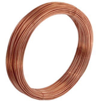
- Copper wire - thick winding wire. Alternative - all kinds of thinner stranded wires are twisted. For strength and reliability, they are soldered with solder so that copper does not oxidize, and the conductor does not "get loose".
- Dielectric base... It can be any board, plywood, chipboard, fiberboard, as well as home-made or industrial getinax (or fiberglass), from which printed tracks have been removed. You can also use flat pieces of plastic from old, obsolete electrical appliances.
- Fasteners... Bolts, screws, self-tapping screws, lock washers, nuts. Stock up on the right amount. Perhaps, plastic "assemblies" will also come in handy.
- Coaxial cable (with a characteristic impedance of 50 or 75 ohms), plug (for the antenna socket of your receiving device).
- The simplest locksmith tools. It can be flat and curly screwdrivers, pliers, side cutters, hacksaws for metal and wood, possibly an adjustable wrench and a hammer. A grinder and a drill will also speed up the manufacturing process of the antenna.
- Waterproof varnish or paint. Conductors and the place where the cable is connected to them must be painted. This will protect them from corrosion caused by water droplets.
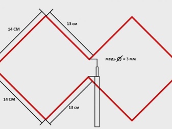
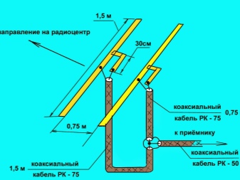
If you are not a radio specialist, then take a ready-made drawing. An example is a loop antenna. To craft it, do the following.
- Guided by the dimensions from the drawing, bend a working element - a "butterfly" from a copper wire.
- Place it on a sturdy dielectric base by tying it to a wooden or plastic plate with the help of "monitors". A more "advanced" option is vertical supports at the edges and in the center of the figure eight on a screw mount. So in the 1990s did the "home-made" people who made antennas for the reception of UHF TV channels.
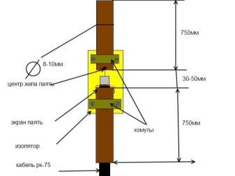
- Solder the cable... The central core is connected to one side of the antenna, the braid to the other. There should be a gap of up to 1 cm between the parts of the figure eight and them. The dipole antenna is connected to the cable in the same way.
- Color the whole structure.
- After the paint has dried fasten the structure to a pole or pipe. Tie the cable at several points to the pole.
- Attach the plug to the other end of the cable and raise the antenna higher. Point it at the broadcasting city. If the distance is too great, there is no direct signal - they find a reflected one, for example, from a mountain or the tallest building near you.
Antenna check is performed by the quality of reception of the desired radio station. Radio transmitters today are located in arbitrary cities and regional centers - many private radio broadcasters have appeared, earning money from advertising. The radio stations are located not in the place of the city TV tower (on the "television center" hill), but on a low mast about 30 m high. Not everyone wants to rent the "strategic height" of a city or region, broadcasting from the roof of a 9 ... 25-storey building through a low-power W) FM transmitter.
There should be as little noise as possible in the background of a radio broadcast. The radio must be in stereo. It is impossible to receive a stereo transmission when the signal is weak - there is a noticeable noise in its background. Rotate the antenna until you get the best quality. If the station is too far away, but the noise remains - connect the radio amplifier to the cable break, next to the antenna.
A universal cable will help here, in which, in addition to the "coaxial", a pair of additional wires is hidden under the outer protective sheath. The power line is isolated from the center conductor by the braid of the main radio cable. If there is no such cable, the amplifier is powered by wires to the radio receiver nearby, separately.
Amplifiers require a constant voltage of several volts (no more than 12, such are car radio amplifiers) and a current strength of several tens of milliamperes.
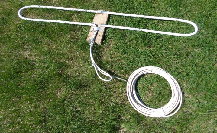
You can find out how to make an FM antenna with your own hands in 15 minutes below.


The comment was sent successfully.