All About Tapping Sizes
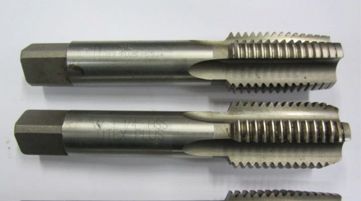
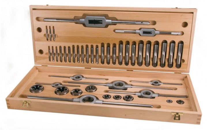
Knowing everything about the sizes of taps for tapping is very useful for everyone who has to create this very thread all the time. You need to carefully consider the standard pitch of taps M6 and M8, M10 and M12, M16 and M30. You will also have to study the inch dimensions and the principles of selecting the drill section.
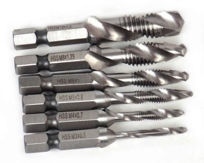
Standard tap parameters
Special marking equipment for threading is clearly sized. Quantity is measured in several ways. The main thread index, even for metric products, is set on an inch scale. This is not difficult to see in any description of such products. So, for M6 taps, the thread is made with a section of 0.1 cm. In this case, the size of the hole for threading can be from 4.8 to 5 mm.
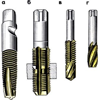
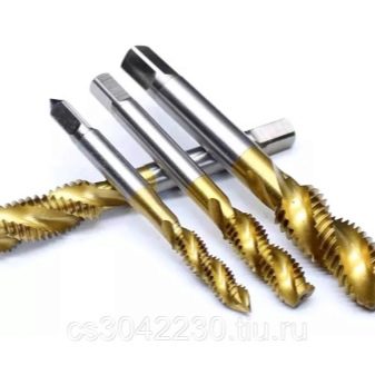
For M6 category products, the typical basic pitch will be 1.25 mm. And the punched passage for a product with a diameter of 8 mm reaches 6.5-6.7 mm. For smaller structures (M5), such dimensions are taken to coincide with 0.8 mm, 4.1-4.2 mm, respectively. It is interesting to compare this model with a large serial sample - M24. The step of forming the grooves will be 3 mm, and the landing square is taken equal to 1.45 cm.
The metal marking device, type M12, cuts through 1.75 mm. The hole section will be 9.9 or 10 mm. For smaller M10, such indicators are taken equal to 1.5, 8.2 and 8.4 mm, respectively (in the case of the minimum and maximum passage).
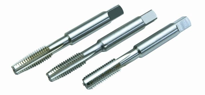
Sometimes M16 taps are used. These tools allow you to scratch threads at 2 cm intervals, with channels of 1.35 cm minimum and 1.75 cm maximum.
In some cases, it becomes necessary to make grooves at intervals of 2.5 mm. Then taps from the M20 category come to the rescue. During their operation, passages with a cross section of at least 1.5 cm are formed. Dimensions and operating parameters (in centimeters) of some other marking devices are shown in the table below. It is important to understand that everything that has been said applies only to metric threads.
|
Type index |
Slot stroke |
Channel section |
|
M7 |
0,1 |
0,595 |
|
M9 |
0,125 |
0,77 |
|
M2 |
0,04 |
0,16 |
|
M4 |
0,07 |
0,33 |
|
M11 |
0,15 |
0,943 |
|
M18 |
0,25 |
1,535 |
|
M22 |
0,25 |
1,935 |
|
M24 |
0,3 |
2,085 |
|
M30 |
0,35 |
2,63 |
|
M33 |
0,35 |
2,93 |
|
M42 |
0,45 |
3,725 |
|
M48 |
0,5 |
4,27 |
|
M60 |
0,55 |
5,42 |
|
M68 |
0,6 |
6,17 |
Typical shank dimensions are also normalized (in millimeters):
- 2.5x2.1 (for taps no larger than M1.8);
- 2.8x2.1 (M2-M2.5);
- 3.5x2.7 (only for M3 taps);
- 4.5x3.4 (only for marking equipment M4);
- 6x4.9 (from M5 to M8 inclusive);
- 11x9 (M14);
- 12x9 (M16 only);
- 16x12 (only M20);
- 20x16 (markers M27).
There are also shanks:
- 14x11;
- 22x18;
- 25x20;
- 28x22;
- 32x24;
- 40x32;
- 45x35.
Inch dimensions
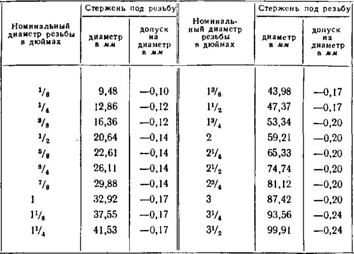
They are typical for products supplied from the USA and Great Britain. If the cross-section of the grooves is 3/16, then the hole is laid strictly from 0.36 to 0.37 cm. Quite popular 1/4 inch taps make channels of 5-5.1 mm, and for products of the 3/8 class, these indicators will be 7, 7 and 7.9 mm, respectively. The groove spacing (in millimeters) will be equal to:
- 1,058;
- 1,27;
- 1,588.
The 1/2 format assumes a groove spacing of 2.117 mm. In this case, a passage of 1.05 mm is laid. Inch taps have a pitch of 3.175 mm. The hole reaches 2.2 cm in diameter. The largest models are in the 17/8 category. The thread pitch is 5.644 mm, and the hole diameter will reach 4.15 cm.
It should be noted that along with metric and inch marking devices, there are also those that are designed to mark holes in pipes. For a 1/8-inch tool, the travel is 28 threads per inch. If it is 1/2 grade, then the threads are formed at intervals of 14 turns per inch.
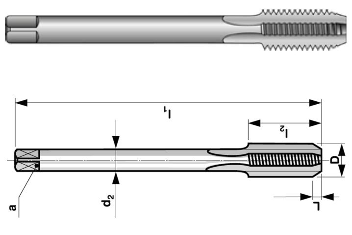
The sections of the rifling themselves will be equal to 0.8566 and 1.8631 cm.A 2-inch pipe tap makes 11 turns per inch, and the notch section is assumed to be 5.656 cm.
How to choose the drill diameter?
The size of the holes today continues to be determined according to the GOST of the distant 1973. Although this standard has been revised several times, its norms have consistently confirmed their relevance. In terms of work in industry, energy and other areas, nothing has changed. The universal approach is typical for the processing of both ferrous and non-ferrous metals. To determine the parameters required for cutting an internal thread, start by drilling the landing area.
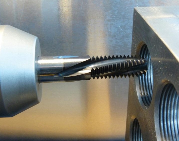
This is done with a double radius. Carefully check that the channel when drilling is 0.1-0.2 cm narrower than the required section. Otherwise, it will not work then to make turns with exactly the same dimensions. The selection of drills is carried out taking into account the measuring standard, on a millimeter or on an inch scale. The number of threads for entry should also be taken into account.
One and the same turn can be designated in different ways. It is installed by measuring the gap between the adjacent sidewalls on the profile. First, 10 threads are counted. Then the number of millimeters between them is estimated and this figure is reduced by 10 times. The stroke is calculated in the same way, but it is already calculated by the turns of one thread.
The properties of brittle and hard alloys differ from those of soft ductile metals. This is often forgotten by people choosing taps for threading. So, in soft materials for the M8 thread, a hole of 6.8 mm is needed. In solid - 0.1 mm less.
It is also advised to take into account the maximum deviations in diameter set in GOST, and pay attention to the difference between conventional and chipless taps.


The comment was sent successfully.